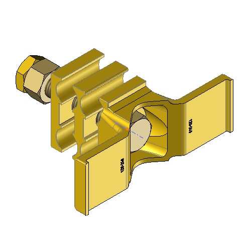
Discover
EARTHING AND GROUDING OF SUBSTATION
Discover overview, principles and grouding products dedicated for substation
Protection of electrical Substations
Equipotential networks on electrical substations
Introduction to permanent grounding of substations
The performance of an equipotential network is linked to the quality of the connections of the constituent elements. Generally speaking, the various metal elements and grounds of a source station must be connected to the general grounding network. It is essential that the connections have high mechanical strength, electrical contact and corrosion resistance.
On the following pictures, some examples of maintenance and installation of a buried grounding network on an electrical transformer station:
Objectives of permanent grounding for substations
In principle, a safe grounding design for substations has the following two objectives:
- Provide means to carry electrical currents into the earth under normal and fault conditions without exceeding operating and equipment limits or impairing continuity of service
- Ensure that a person in the vicinity of the grounded facilities is not exposed to the danger of a critical electric shock
A practical approach to safety associated with grounding concerns and aims to control the interaction of two grounding systems, as follows:
- Intentional grounding, consisting of grounding electrodes buried at a certain depth below the surface of the ground
- Accidental grounding, temporarily established by a person exposed to a potential difference in the vicinity of a grounded installation
It should never be assumed that any earthed component can be safely touched. A low earth resistance on a transformer station is not, in itself, a guarantee of safety. There is, in fact, no simple relationship between :
- The resistance of the entire grounding system
- The maximum shock current to which a person may be exposed
Therefore, a substation with a relatively low ground resistance may be unsafe, while another substation with a very high resistance may be safe or can be made safe by protective measures and/or careful design.
Principle of Protection
The MALTEP range for electrical substations
Schematic diagram for the protection of substations
Earth clamp
View our earth clamp products category earth clamp products
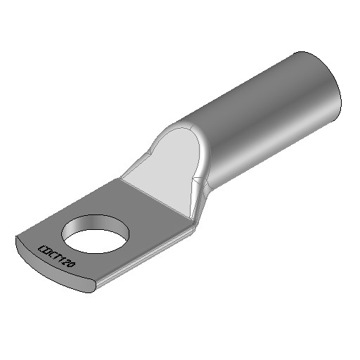
Straight compression lugs with long barrel
View our compressions lugs for substations category
Exothermic welding
View our Exothermic welding category
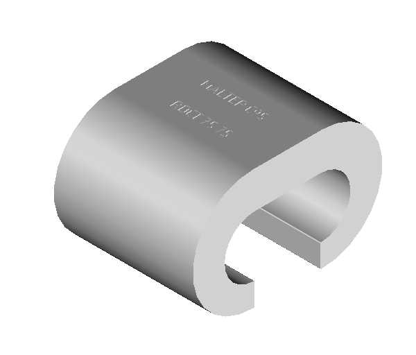
C crimp connectors
View our C crimp connectors category
Cable holders
View our cable holders category
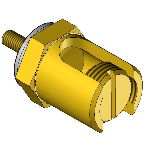
Earth clamps
View our Earth clamps category
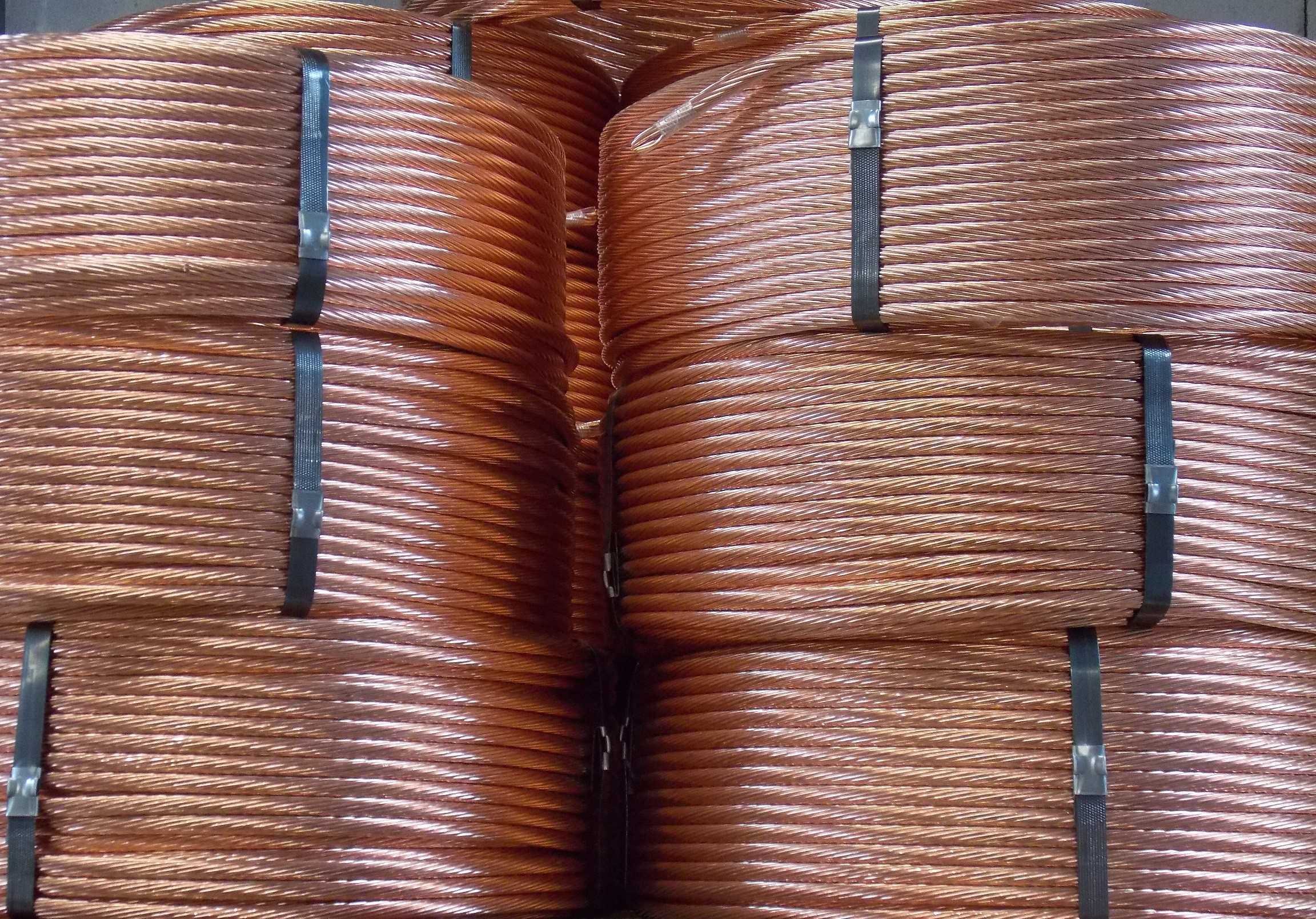
Conductors
View our Conductors category
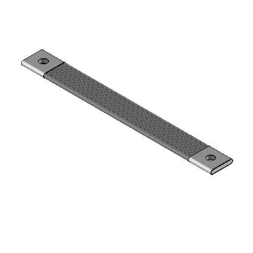
Earth braids
View our earth braids category
Earth clamps
Discover our range dedicated to sub-stations
Earth clamps for substation
The earth clamp for substations is a set of copper alloy blocks holding the earthing circuit loop
MALTEP / RTE equivalents
Equivalences between MALTEP commercial references and RTE / CNER references | |
CPAR50-120L | STN-75/116 - A1 mark |
CPAR150L | STN-146Â - A2 mark |
CPAR185L | STN-182Â - A3 mark |
Copper alloy earth clamps and bolts for metalic structures up to 20mm thick. Icc (A) withstand from 30 to 40 kA/1 s and 63kA/0,5s
CPAR50-120L
Double earth clamps for subsations
Similar to the earth clamp, it includes an additional set of copper alloy block allowing an additionnal earthing circuit loop
MALTEP / RTE equivalences
Equivalences between MALTEP commercial references and RTE / CNER references | |
2CPAR50-120L | STND-75/116 - C1 mark |
2CPAR150L | STND-146 - C2 mark |
2CPAR185L | STND-182 - C3 mark |
Copper alloy earth clamps and bolts for metalic structures up to 20mm thick. Icc (A) withstand from 30 to 40 kA/1 s and 63kA/0,5s
2CPAR50-120L
Winged earth clamps for substations
Similar to the earth clamp with additional wings for temporary earthing connection during maintenance work on the earthing circuit via earth clamp systems
MALTEP / RTE equivalences
Equivalences between MALTEP commercial references and RTE / CNER references | |
CLPAR50-120L | STA-2/75/116 |
CLPAR150L | STA-2/146 |
CLPAR185L | STA-2/182 |
Copper alloy earth clamps and bolts for metalic structures up to 20mm thick. Icc (A) withstand from 30 to 40 kA/1 s and 63kA/0,5s
CLPAR50-120L
Doubled winged earth clamps for substations
Similar to the winged earth clamp, it includes an additional set of copper alloy block allowing an additionnal earthing circuit loop
MALTEP / RTE equivalences
Equivalences between MALTEP commercial references and RTE / CNER references | |
2CLPAR50-120L | STDA-2/75/116 - B2 mark |
2CLPAR150L | STDA-2/146 - B3 mark |
2CLPAR185L | STDA-2/182 - B4 mark |
Copper alloy earth clamps and bolts for metalic structures up to 20mm thick. Icc (A) withstand from 30 to 40 kA/1 s and 63kA/0,5s
2CLPAR50-120L
MALTEP Earth clamp products range
Crimp connectors
Discover our range dedicated to sub-stations
Straight compression lugs with lon barrel for substation
The straight compression lugs is used for connecting electrical cables to structures, equipotential bonding bars, or to the terminals of electrical equipment.
MALTEP / RTE equivalences
Equivalences between MALTEP commercial references and RTE / CNER references | |
CDCT75-10 or COTD75-10 | CDCT75-10 - F1 mark |
CDCT75-12 or COTD75-12 | CDCT75-12Â - F1 mark |
CDCT120-10 or COTD120-10 | CDCT120-10Â - F2 mark |
CDCT120-12 or COTD120-12 | CDCT120-12Â - F2 mark |
COTD150-12 | CDCT146-12 - F2 mark |
COTD150-16 | CDCT146-16 - F2 mark |
COTD185-14 | CDCT182-14 - F2 mark |
COTD185-16 | CDCT182-16 - F2 mark |
Tinned copper compression lugs with marking for crimping. Icc (A) rating of 30 to 40 kA/1 s and 63kA/0.5 s
Copper compression sleeves for substations
The copper sleeve for grounding conductor allows the end-to-end connection of two grounding cables of identical section. The connection is made by crimping and requires a crimping tool and a die adapted to the size of the sleeve. As an alternative to the sleeve, aluminothermic welding can also be performed.
MALTEP / RTE Equivalences
Equivalences between MALTEP commercial references and RTE / CNER references | |
MCL75 | MCL75 - M1 mark |
MCL120 | MCL120 - M2 mark |
MCL150 | MCL150 - M3 mark |
MCL185 | MCL185 - M4 mark |
Copper sleeves, Icc (A) rating from 20 to 40 kA/1 s and 63kA/0.5 s depending on the reference
C crimp connectors for substations
The C crimp connector allows the interconnection of two grounding cables without interrupting them or the main cable. The connection is made by crimping and requires a crimping tool and the appropriate die set for the size of the C crimp connector. The C crimp connector can be manufactured with copper or tinned copper, tinned copper is preferred especially when it can be in contact with a metal frame. As an alternative to the C crimp connector, exothermic welding can also be performed.
MALTEP / RTE Equivalences
Equivalences between MALTEP commercial references and RTE / CNER references | |
C95• | RDCT-75/75 - J1 mark |
C120• | RDCT-116/75 - J2 mark |
C120• | RDCT-116/116 - J3 mark |
C150• | RDCT-146/75 - J4 mark |
C150• | RDCT146/146 - J5 mark |
C185-95• | RDCT182/75 - J6 mark |
C185• | RDCT182/182 - J7 mark |
C crimp connectors in copper or tinned copper, Icc (A) rating from 20 to 40 kA/1 s and 63kA/0.5 s depending on the reference
MALTEP Crimp connectors products range
Cable holders
Discover our range dedicated to sub-stations
Cable holders for substation
Cable holders are usually used for grounding and equipotential bonding of metal trunking.
MALTEP / RTE equivalences
Equivalences between MALTEP commercial references and RTE / CNER references | |
SEF95-7/2RBM | SF12.7+BM - L1 mark |
SEF120-7/2RBM | SF14.7+BM - L2 mark |
SEF150-7/2RBM | SF16.7+BM - L3 mark |
SEF185-7/2RBM | SF20.7+BM - L4 mark |
Supplied with stud, nuts and 2 bimetallic washers dia 30mm in copper/aluminum. The useful length of the stud is suitable for mounting on frameworks with a maximum thickness of 12mm.
MALTEP cable holders products range
Earth braids
Discover our range dedicated to sub-stations
Earth braids for substation
Earth braids are used to protect against electrostatic surges, lightning and grounding of electrical equipment. Earthing braids are connected between equipment and the ground and transfer electrical surges to ground or to other components capable of absorbing significant amounts of transient voltage.
MALTEP / RTE EquivalenceÂ
Equivalences between MALTEP commercial references and RTE / CNER references | |
TME75300-12 | TME75300-13 - S1 mark |
TME75500-12 | TME75500-13 - S1 mark |
TME75700-12 | TME75700-13 - S1 mark |
TME75900-12 | TME755900-13 - S1 mark |
TME1205300-12 | TME120300-13 - S2 mark |
TME120500-12 | TME120500-13 - S2 mark |
TME120700-12 | TME120700-13 - S2 mark |
TME120900-12 | TME1205900-13 - S2 mark |
TME150300-12 | TME150300-13 - S3 mark |
TME150500-12 | TME150500-13 - S3 mark |
TME150700-12 | TME150700-13 - S3 mark |
TME150900-12 | TME1505900-13 - S3 mark |
TME185300-12 | TME185300-13 - S4 mark |
TME185500-12 | TME185500-13 - S4 mark |
TME185700-12 | TME185700-13 - S4 mark |
TME185900-12 | TME1855900-13 - S4 mark |
Tinned copper earth braids. Icc (A) from 20 to 40 kA/1 s and 63kA/0.5 s depending on the cross-section
MALTEP Earth braids products range
Bimetal
Discover our range dedicated to sub-stations
Bimetallic plates and washers for substation
Bimetallic plates and/or washers are mounted with lugs or between earth clamps and galvanized steel frames to reduce corrosion.
See our Galvanic Corrosion page for a detailed description.
MALTEP / RTE Equivalence
Equivalences between MALTEP commercial references and RTE / CNER references | |
PBM14 | PBST1/12.14 - E1 mark |
PBM16 | PBST1/16 - E2 mark |
RBM14 | PBST2/12.14 - E3 mark |
RBM16 | PBST12/16 - E4 mark |
Composition 15% copper and 85% colaminated aluminum
MALTEP bimetallic plates and washers products range
Appendix: Earthing source substation fences
Find out how to ground your source station fences
🔹🔸 In order to guarantee the safety of people who may be circulating in or around the enclosure of a source substation, it is vital to properly ground your fences.
🔹🔸 Proper earthing reduces the risk of fire or material destruction in the event of a power surge or lightning strike. But also to reduce the risk of injury or death due to high contact or step voltage.